

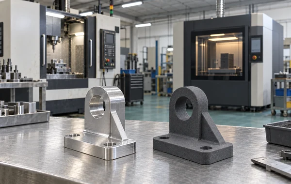
CNC Machining vs. 3D Printing: How to Choose for a Prototype
Choose CNC machining when the prototype must closely represent a final part made from engineering metal or plastic, hold important dimensions, provide machined mating surfaces or support meaningful mechanical testing. Choose 3D printing when you need fast design iteration, complex geometry, internal channels, several design variants or a form-and-fit model without machining every feature.
The deciding question is what the prototype has to prove. An enclosure fit check and a load-bearing aluminum bracket are both prototypes, but they call for different evidence and often different processes.
CNC machining vs. 3D printing at a glance
| Decision factor | CNC machining is often the stronger starting point when… | 3D printing is often the stronger starting point when… |
|---|---|---|
| What you need to learn | You need to test material behavior, fits, threads, sealing surfaces or production-like machined features | You need to check shape, ergonomics, packaging space, assembly sequence or several design ideas |
| Material | The specified metal or engineering plastic is available as plate, block or bar stock | A suitable printing resin, filament, powder or metal process matches the test objective |
| Geometry | The part has machinable faces, bores, pockets, turned features and accessible tool paths | The part has organic forms, internal passages, lattices or geometry that would require several CNC setups |
| Critical dimensions | Datum relationships, bores, threads and mating surfaces need close control in the prototype | Most dimensions are non-critical, or only selected features require secondary machining |
| Surface and appearance | A machined surface or production-relevant finish is part of the evaluation | Layer lines, powder texture or support marks are acceptable, or post-processing can create the required appearance |
| Quantity and iteration | The design is stable enough to justify programming, setup and workholding | The design is still changing, several variants are needed or setup should be kept minimal |
Use the table to narrow the options, not to select the process on its own. An SLA appearance model and a DMLS functional part are both “3D printed,” yet they behave very differently. A simple machined part may also arrive before a print that needs a long build and hours of finishing. The actual files and test plan still need review.
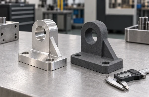
1. Define what the prototype must prove
A prototype should answer a specific question. Before comparing quotations, write down the decision that will be made after the part is tested.
Common prototype objectives include:
- Checking overall size, proportion, color and visible surfaces
- Confirming fit with an enclosure, mating component or installation space
- Finding assembly problems such as blocked fasteners or awkward cable routes
- Testing motion, sealing, load, heat transfer or repeated use
- Checking how the specified alloy or polymer behaves in the expected environment
- Confirming that the design can be made, inspected and finished by the intended production route
If the next decision is mainly about shape, a 3D-printed part may provide enough evidence. If the decision depends on the final alloy, a precision bore or a threaded interface, a CNC-machined prototype may reduce the gap between the test part and the intended production part.
The same project can need both. An early printed model may expose an interference problem before money is spent on a machined version. The later CNC part can then validate the corrected geometry in the required material.
2. Understand the basic process difference
CNC machining is subtractive. A cutting tool removes material from stock while the machine, fixture and program control the part geometry. Milling creates faces, pockets, holes and contoured surfaces; turning is suited to rotational features such as shafts, sleeves and threaded cylindrical parts.
3D printing is additive. It builds geometry from digital model data, usually layer by layer. The exact mechanism varies. FDM deposits thermoplastic material, SLA cures resin, SLS and MJF process polymer powder, and DMLS produces metal parts through a powder-bed process. NIST’s additive manufacturing overview explains the layer-by-layer principle and why additive methods can produce complex designs.
The process changes the material condition, design constraints, support or fixturing needs, surface texture, inspection plan and post-processing work.
3. Compare material conditions
Material is often the deciding factor for a functional prototype.
A CNC part begins as bulk stock. If the prototype is intended to represent a production-machined aluminum, stainless steel, titanium, POM, PEEK or nylon component, machining the specified grade and condition usually gives the test team a more relevant material comparison. Heat treatment, grain direction, stock form and finishing can still affect performance, so the RFQ should name the complete material specification rather than “aluminum” or “plastic.”
A 3D-printed part uses a process-specific feedstock and build cycle. FDM thermoplastics, SLA resins, SLS or MJF nylon and DMLS metal are not interchangeable. A familiar material label does not prove that a printed part will behave like an injection-molded, extruded or machined version of a material with a similar name.
Ask these questions before using a printed prototype for functional testing:
- Is the exact material grade known?
- Are the published properties measured in the relevant build orientation?
- Will layer direction affect the expected load?
- Are post-curing, heat treatment or conditioning required?
- Will the test expose the part to heat, moisture, chemicals, UV or repeated loading?
- Does a certificate, traceable material lot or specific test method apply?
Printed parts can be functional when the material data and build conditions match the test. For an enclosure clearance check, production-equivalent mechanical properties may add cost without changing the answer. A safety-critical load test needs much closer review of material equivalence and process qualification.
4. Let geometry guide the process
CNC machining needs tool access and secure workholding. Deep narrow pockets, small internal corner radii, very thin walls and features hidden behind other geometry can increase the number of setups, require special tools or make a design impractical to machine as one piece.
For a CNC-friendly prototype:
- Use internal corner radii that allow a suitable end mill to reach the feature.
- Avoid deep pockets unless they are functionally necessary.
- Leave enough wall thickness for stable machining and clamping.
- Give tools and inspection equipment access to critical features.
- Separate a complex part into machinable components when assembly does not compromise the test.
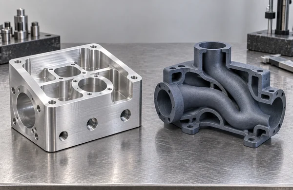
Additive processes do not need a cutting tool to reach every surface, so they can handle enclosed passages, organic transitions, lattices and consolidated assemblies. They still have their own restrictions. Build orientation can change support needs, surface condition, dimensional behavior and mechanical response. Trapped powder, unsupported areas, drainage, minimum wall thickness and access for support removal all need review.
For a 3D-print-friendly prototype:
- Choose orientation based on function as well as appearance.
- Provide access for support removal, resin drainage or powder removal where the process requires it.
- Review thin walls, small holes and long unsupported spans.
- Allow for inserts or secondary machining where threads and mating features need more control.
- Check whether internal channels can be cleaned and inspected.
Review the actual geometry before choosing. A visually complex exterior may still be machinable with 5-axis equipment, while a simple-looking printed part may become difficult because of orientation, support removal or distortion.
5. Separate critical dimensions from the rest of the model
“High accuracy” is not a complete requirement. A useful prototype drawing identifies the dimensions that affect assembly or function and gives realistic acceptance limits for them.
CNC machining often suits datum-controlled features, precision bores, bearing seats, threads and sealing faces. Even then, the achievable result depends on part size, material, geometry, wall thickness, setup and inspection method. A general capability figure should never be copied onto every dimension of a drawing.
3D printing accuracy varies by process, machine, material, orientation, feature type and location in the build. A process that reproduces small visual details well does not automatically control every overall dimension or hole to the same level. Holes, threads and flat mating surfaces may need allowance, inserts or secondary machining.
A practical drawing separates the features by how they will be used:
- Put a datum and tolerance on features that control fit, sealing, alignment, motion or safety.
- Give a wider acceptable range to features that need repeatable control but do not drive the test.
- Mark dimensions used only for reference, overall shape or appearance accordingly.
This classification helps the manufacturer decide whether the part should be CNC machined, printed, printed and then machined, or redesigned for a different test method.
6. Decide how much surface finish matters
As-machined CNC parts normally show a toolpath pattern. Bead blasting, anodizing, passivation, plating, polishing and other finishing options may be available depending on the material and specification. If a surface seals, slides, reflects light or remains customer-visible, mark it on the drawing and define the required condition.
Printed surfaces reflect the selected process. FDM can show layer lines; SLA parts may show support and post-cure effects; SLS and MJF often have a fine powder-based texture; DMLS surfaces may need support removal, heat treatment, blasting or machining. Painting, polishing, dyeing and vapor smoothing can change appearance, but they also add time and may affect dimensions.
A cosmetic-finish request needs a clear acceptance condition. State:
- Which surfaces are visible
- Whether color or gloss must match a reference
- Where support or witness marks are unacceptable
- Whether sharp edges should be broken or preserved
- Which dimensions apply before or after coating and finishing
A photograph or physical reference sample can be more useful than an adjective such as “smooth.”
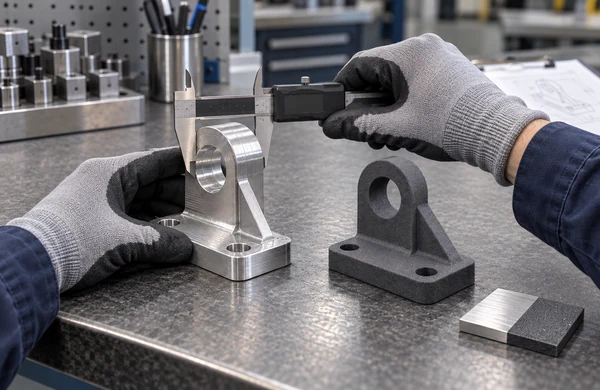
7. Compare total time and total cost
3D printing is often associated with speed because it avoids dedicated cutting tools and complex fixtures. That can be valuable when the CAD model is changing or when several different concepts must be evaluated. But print time is only one part of the schedule. Build preparation, queue time, cooling, depowdering, washing, post-curing, support removal, heat treatment, finishing and inspection may all apply.
CNC machining has programming, setup and workholding effort. Cutting time, stock availability, tool access, number of setups and inspection requirements affect the quotation. For a stable, relatively simple design in available stock, those steps may still lead to a competitive prototype schedule.
Compare quotations using the same scope:
- Required delivery date and destination
- Number of parts and number of design variants
- Material grade and stock or feedstock availability
- Included post-processing and finishing
- Inspection and reporting requirements
- Packaging and shipping
- Any secondary machining, inserts or assembly
There is no universal quantity at which one process becomes cheaper. Part size, build packing, machine time, material, setup and finishing shift the crossover point. Ask for both options when the design and test objective make both technically credible.
8. Use a staged prototype plan when one part cannot answer every question
Trying to make the first prototype look, feel and perform exactly like the final product can slow learning. A staged plan usually makes each build easier to evaluate.
One practical sequence is:
- Print a form-and-fit model to check size, ergonomics, assembly access and interference.
- Correct the CAD model, record what changed and release a new revision.
- Machine the functional prototype in the required bulk material for mechanical, thermal or interface testing.
- Apply the relevant finish, then confirm the dimensions and appearance that matter.
- Review the production route and update the tolerances, inspection points and design details before a pilot build.
Another option is a hybrid part: print a complex near-net geometry, then machine selected datums, bores, threads or sealing surfaces. This can be useful when additive geometry and machined interfaces are both important. It also introduces extra setup, alignment and inspection questions, so the critical features should be agreed before the build begins.
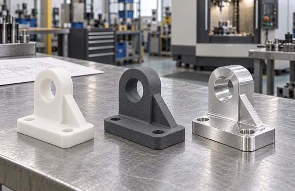
9. Process choices for common prototype situations
| Prototype situation | Likely starting point | Reason to review an alternative |
|---|---|---|
| Handheld enclosure for an ergonomic review | SLA, SLS or MJF, depending on finish and function | CNC may be more relevant if the final enclosure is machined and weight or thermal behavior matters |
| Aluminum mounting bracket for load and thread testing | CNC machining | Metal additive may suit a redesigned lightweight geometry that cannot be machined directly |
| Manifold with curved internal channels | 3D printing, with process-specific channel and cleaning review | CNC may work if the part can be split and sealed without invalidating the test |
| Shaft, sleeve or bushing with concentric features | CNC turning | Printing may help with an early packaging model that does not need the final fits |
| Five geometry variants for an assembly check | 3D printing | Machine the selected revision later if the final material or critical dimensions affect function |
| Metal part with complex body and precision sealing faces | Metal additive plus secondary machining may be considered | Full CNC machining may be simpler if tool access and workholding are reasonable |
Treat these as screening examples. A process recommendation should follow review of the model, drawing, material, quantity, test conditions and delivery requirement.
10. What to send for a useful process review
To compare CNC machining and 3D printing for the same prototype, send one controlled data set and describe what is flexible.
Include:
- Current STEP or other agreed 3D CAD file
- PDF drawing for critical dimensions, datums, threads, finishes and notes
- Part number and revision on every controlled file
- Prototype purpose and the test it must support
- Required and preferred materials, including permitted alternatives
- Quantity now and likely follow-on quantity
- Critical surfaces, fits, interfaces and appearance areas
- Environmental and load conditions relevant to the test
- Inspection, test and documentation requirements
- Required delivery date and destination
If the process is open, say so directly. For example: “Quote the best option for an assembly-fit check, and provide a separate option in 6061 aluminum for functional testing.” That gives the reviewer a clear basis for comparing routes without guessing which requirements can change.
Zenbot China coordinates CNC machining and 3D printing alongside other manufacturing processes. Materials, tolerances, finishes, inspection, quantity and timing are reviewed for each project rather than assumed from a general capability table.
Frequently asked questions
1. Is CNC machining always more accurate than 3D printing?
No. CNC machining often provides a strong route for datum-controlled bores, threads, mating faces and other precision features, but the result still depends on material, geometry, setup and inspection. 3D printing accuracy also varies widely by process, material, orientation and feature type. Compare the critical dimensions on the actual part instead of relying on one general accuracy number.
2. Is 3D printing always faster for a prototype?
No. It can be faster when the design is changing, geometry is complex or several variants are needed without dedicated fixtures. A long build, full machine queue or extensive curing, support removal, heat treatment and finishing can change the schedule. A simple CNC part made from available stock may be faster in some cases.
3. Can a 3D-printed prototype be used for functional testing?
Yes, when the printing process, material, orientation and post-processing match the test. The team should confirm whether layer direction, heat, chemicals, moisture, repeated loading or surface condition will affect the result. A printed fit model and a printed load-bearing component do not require the same material evidence.
4. Should the final prototype use the intended production material?
Use the intended material when the decision depends on its strength, stiffness, temperature response, chemical resistance, wear, weight or finish. For an early appearance or assembly check, a lower-cost substitute may be enough. Record the substitution so nobody treats the test as final-material validation.
5. Can the same CAD design be used for CNC machining and 3D printing?
The same model can be reviewed for both, but it may not be efficient for both. CNC needs tool access, internal radii and workholding; printing needs suitable orientation, wall thickness and support, drainage or powder-removal access. Small design changes can reduce risk and cost while preserving the prototype’s function.
6. When should CNC machining and 3D printing be combined?
Combine them when additive manufacturing provides the necessary geometry but selected datums, holes, threads or sealing surfaces need machining. They can also be used at different development stages: print early versions for rapid learning, then machine the stable design in the required bulk material.
Choose the process around the next decision
Choose the process that gives the next design or purchasing decision enough evidence. For an early fit review, that may be a nylon print. For a test involving a thread, bore, sealing face or final material, a machined part is often the more useful sample.
Many teams print an early revision, correct the fit problems it exposes and machine only the design that survives that review. A hybrid build makes sense when additive manufacturing is needed for the geometry and machining is needed on selected interfaces.
To compare suitable processes for a specific part, request a quote with the current CAD model, drawing, quantity, material options and a short description of what the prototype must prove.