


PCB Assembly File Checklist: Gerber, BOM and Placement Data
For a PCB assembly quote, send a controlled package containing the Gerber fabrication data, drill files, bill of materials (BOM), component placement data, assembly drawings, board specifications, quantities and test requirements. Gerber files define the bare board; the BOM identifies what must be fitted; placement data tells the assembly equipment where each machine-placed component belongs. None of these files replaces the others.
A quotation can sometimes begin with an incomplete package, but missing data usually turns into engineering questions, assumptions or exclusions. The safest approach is to export all files from the same released design revision, check them together, and include a short readme that identifies the job, revision and any approved exceptions.
PCB assembly file checklist at a glance
| File or instruction | Main purpose | Minimum information to check |
|---|---|---|
| Gerber files | Define copper, mask, legend, paste and mechanical artwork | Correct layer set, board outline, revision and units |
| NC drill files | Define plated and non-plated holes and slots | Drill units, tool data, PTH/NPTH handling and slot representation |
| Bill of materials | Defines fitted parts and sourcing rules | Reference designators, quantity, manufacturer, manufacturer part number and DNP status |
| Placement data | Locates machine-placed components | Designator, X/Y position, rotation, side, units and origin |
| Assembly drawings | Communicate orientation and special assembly intent | Pin 1, polarity, DNP parts, mechanical items and hand-assembly notes |
| Fabrication notes | State construction requirements not contained in artwork | Material, thickness, copper, finish, stack-up, impedance and applicable acceptance requirements |
| Test and programming package | Defines post-assembly verification | Test method, limits, fixtures, firmware, connector pinout and reporting needs |
| Readme or release note | Controls the data set | Part number, revision, quantity, file list, contacts and approved deviations |
Use this as a release check, not as a substitute for supplier review. Board technology, component risk, sourcing responsibility and test scope can change what must be included.
1. Start with one controlled release
The most important rule is simple: every file in the package should describe the same board revision. A correct Gerber set paired with an old BOM can be more dangerous than an obviously missing file because the inconsistency may not be visible until purchasing or assembly begins.
Put the project name, board part number and revision in the archive name and readme. If the design has separate fabrication and assembly revisions, state both. Record the export date and identify the ECAD tool only as supporting information; the released outputs, not the software name, should control the build.
A practical archive might contain these folders:
01_Fabricationfor Gerber, drill, stack-up and fabrication notes02_BOMfor the controlled component list and approved alternatives03_Placementfor pick-and-place or centroid data04_Assemblyfor assembly drawings, polarity notes and mechanical instructions05_Testfor firmware, test instructions, limits and fixture information06_Releasefor the readme, revision history and approval record
Avoid mixing superseded files into the release archive. If an old revision must be included for comparison, place it in a clearly named reference folder and state that it is not for production.
2. Build a complete Gerber and drill package
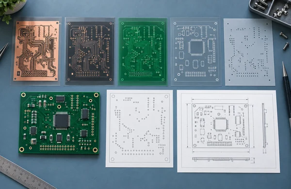
Gerber is a manufacturing data format for PCB artwork. The current specification and supporting resources are maintained by Ucamco. A normal fabrication set may include:
- Top and bottom copper, plus every internal copper layer
- Top and bottom solder mask
- Top and bottom silkscreen or legend when used
- Top and bottom solder paste layers when a stencil or paste definition is required
- Board profile, routing or mechanical layer
- Plated and non-plated drill data, including routed slots where applicable
- Fabrication drawing or notes for dimensions, tolerances and special features
- Stack-up and controlled-impedance information when these are design requirements
The exact filenames depend on the ECAD exporter, so clear layer identification matters more than one naming convention. Do not rely on an unlabeled mechanical layer to communicate the finished outline. The profile should be closed, unambiguous and consistent with the drawing.
Before release, open the exported data in an independent Gerber viewer. Check the overall outline, copper layers, mask openings, legend orientation, drilled holes, slots and any routed cutouts. This catches problems such as a missing internal layer, mirrored artwork, duplicate outlines or an obsolete manufacturing panel.
Extended formats can carry more structured information. Gerber X2/X3, a Gerber job file, ODB++ or IPC-2581 may reduce manual interpretation, but acceptance varies by workflow. Confirm the preferred format with the manufacturer instead of assuming an intelligent data package replaces every drawing or purchasing instruction.
3. Make the BOM purchasable, not merely readable
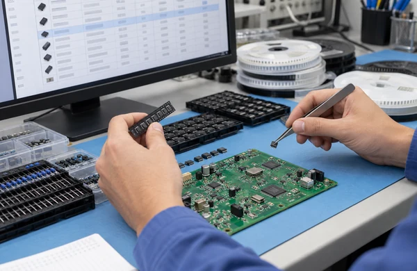
A BOM should allow a buyer to identify the intended component without guessing. A description such as “10 k resistor” is not enough when package, tolerance, power rating, temperature coefficient or qualification status affects function.
For each fitted line, include:
- Reference designator or grouped designators
- Quantity per assembled board
- Manufacturer name
- Exact manufacturer part number
- Clear component description
- Package or footprint
- Value and relevant electrical or mechanical attributes
- Fitted or do-not-populate status
- Approved alternative part numbers, if any
- Sourcing responsibility: customer-supplied, manufacturer-sourced or either
- Notes for programmed, serialized, matched or controlled parts
Keep one manufacturing part number per BOM line. If two approved parts are interchangeable, list the primary part and alternatives in dedicated fields rather than combining several part numbers into one ambiguous cell.
Use a consistent DNP rule. Do not leave the manufacturer to infer that a blank manufacturer part number means “do not fit.” Mark DNP items explicitly, and make their status agree with the assembly drawing and placement file.
4. Control substitutions before purchasing starts
Component availability can change between quotation and build. The data package should say who may propose an alternative, who approves it and what evidence is required.
Useful rules include:
- No substitution without written approval
- Passive substitutions allowed only within stated electrical, package and environmental limits
- Alternate manufacturer part numbers already approved in the BOM
- Customer approval required for lifecycle, country-of-origin or traceability changes
- No broker sourcing unless specifically authorized
- Date-code, moisture-sensitivity or packaging requirements identified where relevant
Do not use “equivalent accepted” as a complete instruction. Equivalence may involve fit, form, function, firmware, safety approvals, RF behavior, thermal performance and long-term availability. State the parameters that matter to the design.
If a part must be programmed, provide the firmware file, checksum or version identifier, programming method and labeling requirement. Keep firmware under the same release control as the hardware files.
5. Export placement data with a defined origin and rotation
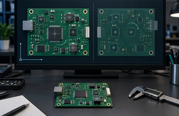
Placement data is also called a pick-and-place file, centroid file, XY file or CPL. It normally contains one row per placed reference designator. At minimum, include:
- Reference designator
- X coordinate
- Y coordinate
- Rotation
- Board side or layer
- Units
State the coordinate origin and make it consistent with the assembly drawing or fabrication data. A clear origin might be a tooling hole, board corner or defined design datum. Do not change the origin after generating only part of the release package.
Rotation conventions differ between ECAD tools and machine libraries, especially for bottom-side components. A placement file therefore needs visual comparison against the assembly drawing. Check several asymmetric parts, including polarized capacitors, diodes, connectors and ICs with an obvious pin 1.
Mechanical items and hand-inserted parts may not appear in automated placement data. Identify connectors, shields, fasteners, press-fit items, wires and through-hole parts on the assembly drawing and in the BOM even when the placement machine will not use their coordinates.
6. Use assembly drawings to show design intent
The assembly drawing is the human-readable bridge between the digital files and the finished PCBA. It should show the board outline, reference designators and top/bottom views as needed.
Call out:
- Pin 1 and component polarity where orientation may be unclear
- DNP components and unpopulated connector positions
- Through-hole and hand-soldered components
- Connector, switch, display or mechanical alignment requirements
- Wire, cable, shield, heatsink, adhesive or hardware installation
- Areas with height, keep-out or cleanliness restrictions
- Special handling or process notes that are not obvious from the BOM
Do not use a screenshot of the PCB layout as the only assembly instruction. A controlled PDF drawing with a title block, part number and revision is easier to review, archive and compare with the release package.
7. Add the specifications that Gerber data cannot carry alone
Artwork defines geometry, but it does not fully define the required product. State the relevant board and assembly requirements separately.
Depending on the design, these may include:
- Finished board thickness and copper requirements
- Base material or performance requirements
- Surface finish and solder mask or legend requirements
- Stack-up and controlled-impedance targets
- Panelization, breakaway and tooling requirements
- Required acceptance standard, class and revision when contractually applicable
- Solder alloy and any lead-free or material restrictions
- Conformal coating, cleaning, staking or underfill requirements
- Serialization, labels and traceability records
- Packaging, moisture protection and shipping instructions
Only specify requirements that the product actually needs. Copying a demanding standard, tolerance or test onto every drawing can increase cost without reducing the relevant risk.
8. Define inspection, testing and programming scope
“Test the boards” is not a complete requirement. State what should be checked, what constitutes a pass and who supplies the fixture, software and golden unit.
Possible stages include incoming component checks, solder-paste inspection, automated optical inspection, X-ray inspection for hidden joints, in-circuit test, boundary scan, firmware programming and functional test. These methods find different failure modes; one should not be presented as a universal substitute for another.
For a functional test package, include:
- Power input, current limits and safe startup sequence
- Connector pinout and required mating cables
- Test steps and expected results
- Measurement limits and required equipment
- Firmware image, version and programming instructions
- Fixture drawings or interface definition
- Golden sample rules, if used
- Test record, serialization and reporting requirements
If the manufacturer is expected to develop the test method or fixture, state the intended coverage and approval process during quotation.
9. Reconcile the files before sending the RFQ
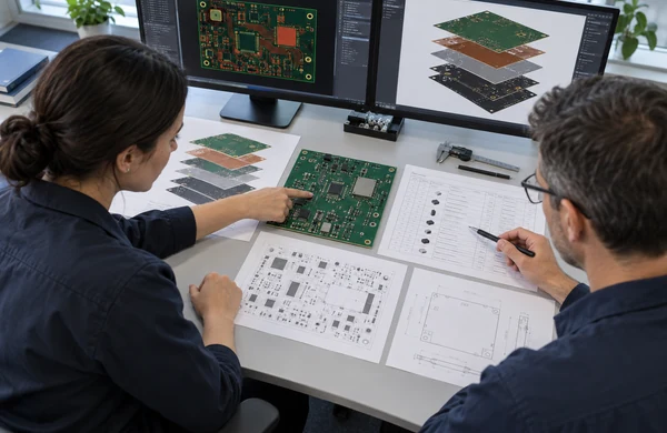
Run a cross-file check rather than reviewing each document in isolation.
- Compare the Gerber outline with the assembly drawing and placement-data origin.
- Compare every fitted BOM designator with the placement data and assembly drawing.
- Confirm that DNP designators are treated consistently in all three sources.
- Check that every placement row has a matching BOM item and valid board side.
- Check asymmetric and polarized components for rotation and pin-1 orientation.
- Confirm the requested quantity means bare boards, assembled boards, panels or complete units.
- Confirm the board revision appears consistently in filenames, drawings and the readme.
- Open the final archive after compression and verify that no required file was omitted.
Differences should be resolved before release or listed as explicit questions. Do not expect the supplier to choose which of two conflicting files is authoritative.
10. Include commercial and delivery information
The technical package should be paired with enough purchasing information to quote the correct scope:
- Prototype and expected follow-on quantities
- Number of unique board types and variants
- Required delivery destination and target date
- Bare-board, consigned, partial-turnkey or full-turnkey sourcing model
- Approved distributors or sourcing restrictions
- Required material, inspection and test records
- Customer-supplied parts and expected arrival condition
- Packaging, labeling and shipment requirements
- Permission and process for engineering questions or proposed alternatives
Zenbot China reviews PCB fabrication, component sourcing, SMT and through-hole assembly, inspection and testing as part of its PCB and PCBA service. The final scope still depends on the released files, quantity, component availability, assembly complexity and test requirements.
Copy-and-send PCB assembly package
Before sending the RFQ, confirm that the archive contains:
- Controlled Gerber and drill files for the released board revision
- Fabrication drawing, stack-up and special board requirements where applicable
- Purchasable BOM with manufacturer part numbers, DNP status and substitution rules
- Placement data with designator, X/Y, rotation, side, units and origin
- Top and bottom assembly drawings with polarity and special assembly notes
- Programming files and controlled firmware version, if required
- Inspection and functional test scope with pass/fail criteria
- Quantity, sourcing model, delivery destination and requested timing
- Readme identifying the authoritative files and revision
- Contact for technical questions and approval of deviations
For a broader mechanical and manufacturing data review, see the manufacturing RFQ checklist. To request a project review, send the current PCB assembly package and identify any files or requirements that are still provisional.
Frequently asked questions
1. Are Gerber files enough for a PCB assembly quote?
Usually not. Gerber and drill files describe the bare board, but assembly also needs a BOM and placement data. Assembly drawings, sourcing rules, quantities and test requirements may also affect the quotation. A supplier can sometimes provide a preliminary estimate from partial data, but assumptions should be identified and resolved before release.
2. Can I request a quote before the placement file is ready?
Possibly, if the BOM and board data are stable enough for a preliminary review. The quotation may exclude machine programming, contain assumptions or remain subject to placement-data review. Send the completed placement file before production and compare it with the final assembly drawing.
3. What should happen when a BOM component is unavailable?
The supplier should report the shortage and propose an alternative only under the project’s substitution rules. The customer should review the relevant electrical, mechanical, environmental, firmware and approval requirements before authorizing the change. Record the approved part number and affected revision.
4. Should I include the schematic and native PCB design files?
They are not always required for a basic build package, but they can help with design-for-manufacturing review, test development and investigation of conflicting data. Share them when the agreed scope requires them and apply appropriate revision and access controls.
5. Should the files describe a single board or a panel?
State clearly whether the released data represents a single board, a customer-designed panel or a board that the manufacturer may panelize. If a panel is controlled by the customer, include the panel drawing, tooling features, breakaway method, fiducials and quantity definition.
6. Does placement data replace an assembly drawing?
No. Placement data provides coordinates and rotation for machine programming, while the drawing communicates orientation, DNP status, hand-installed parts and special assembly intent. Use both and make sure they agree.
Release files that answer the next engineering question
A strong PCB assembly package does not need unnecessary paperwork. It needs one consistent answer for board geometry, component identity, placement, assembly intent, sourcing authority and verification.
Export the files from one released revision, review them together, and state what is fixed versus provisional. That gives the manufacturer a clear basis for quotation and reduces the chance that purchasing or production must resolve design decisions by assumption.